Duke UniversitySeptember 2025 - December 2025
Project Tyr : Jet Engine
Tyr is a low-cost, metal 3D-printed turbojet engine designed for UAVs and single-use missiles, utilizing distributed manufacturing to dramatically reduce part count.
Skills
Additive Manufacturing, Metal 3D Printing, CFD Analysis, ANSYS, Fusion 360, CF Turbo, Turbomachinery Design, Heat Treatment, Precision Machining, Propulsion Systems, Mechanical Engineering, Distributed Manufacturing
This project represents a significant innovation in small-scale jet engine manufacturing, developed in collaboration with Alex Boniske and Kagame Rama Munroe at Duke University. Designed for UAVs and single-use missiles, this metal 3D-printed turbojet aims to democratize access to propulsion technology through distributed manufacturing.
We recently test-fired the first version of the engine. While designed to spin at 110,000 RPM on kerosene, we limited the initial test to under 30,000 RPM using propane due to machining tolerances. The engine struggled to self-sustain, likely due to pressure loss from gaps between the compressor wheel and the housing. This highlighted the challenges in post-machining 3D-printed parts, where resonance can be a nightmare and "nothing is true," meaning even small tolerance errors can render a part useless.
The fundamental innovation lies in our manufacturing approach. By utilizing metal 3D printing for critical components, we reduced the part count from approximately 50 pieces to just 10 major components. This dramatic simplification enables distributed manufacturing, allowing anyone with access to metal 3D printing to produce these engines with minimal machining requirements.
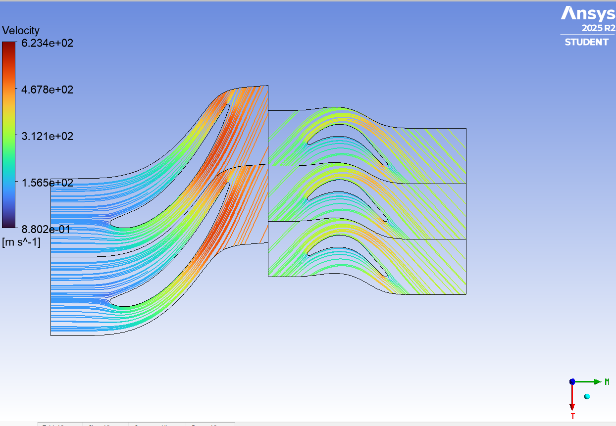
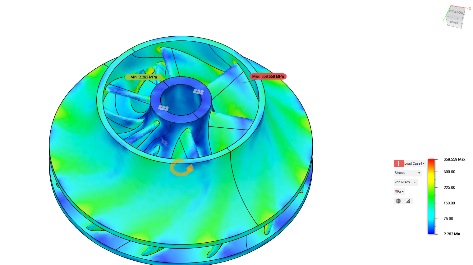
Most of the parts are 3D printed in stainless steel or aluminum and post-machined on a lathe. The shaft is heat-treated 4140 steel, grounded to size. The design phase took about two months and involved many trial and error iterations. We used Ansys and CFturbo for the design of the compressor, diffuser, guide vanes, and turbine. We ran many FEAs and hand calculations for the choice of material and preliminary design.
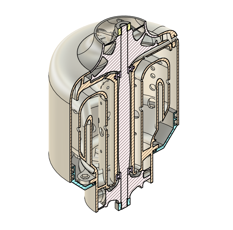
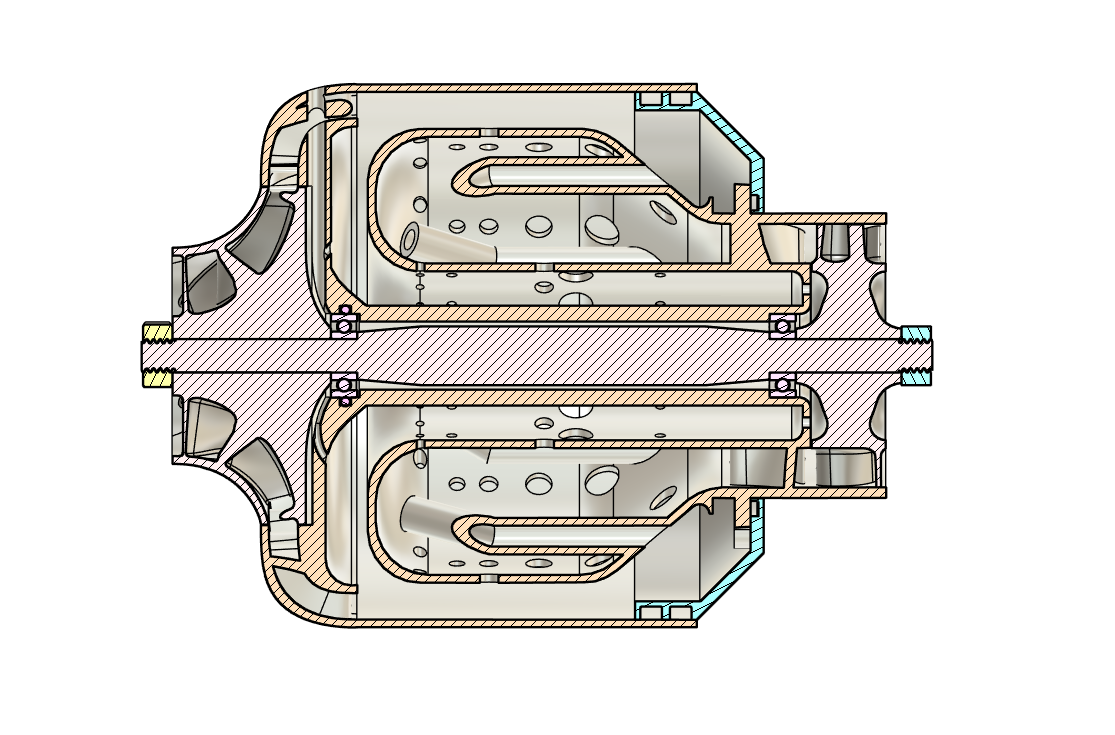
I went with a closed impeller design, which is something I haven't seen before in this context. This was chosen for higher efficiency and, most importantly, because it enabled the engine to be made of only one big housing part, with the impeller and turbine directly attached on both sides. We balanced the turbine and impeller using the rocking method, followed by the fingertip method, which gave satisfactory results for our initial tests.
A turbojet works by compressing air at high pressure, then burning that high-pressure air, and using the energy of the expanding gas to push on the turbine rotor which is connected to the compressor by a shaft, sustaining this cycle. The high-speed air then exhausts, producing thrust.
Built in my dorm and student machine shop (thanks to their help!), this project was a massive undertaking. Thanks to Alex for giving me a hand on some aspects of the CAD. In the end, it didn't fulfill the performance criteria I hoped for, but for a one-man design and build in only four months, I am happy with what I managed to come up with. It explains why less than six countries can actually produce jet engines. I am looking forward to the next semester's new project!